Machined Fins & Bulbs


Download : Machined Fins & Bulbs Info Sheet
Read : Machined Fins & Bulbs Info Sheet
Machining of Bulbs and Fins
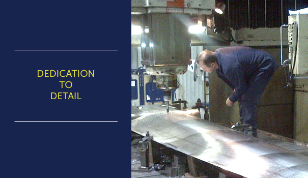
When the keel design requires a machined keel MarsKeel Technology offers the customer (owner, builder or designer) the very finest quality. Our quality begins at the start of the production process, with the raw material used, be it a casting, a billet or a fabrication. This dedication to detail continues throughout the machining processes, usually a minimum of a three-step process, which produces a very high quality keel, fin or bulb.
General Inspection Process
All of our materials are third party-certified as acceptable to ASTM standards (to required material specifications and NDT) The other aspect of our inspections range from a simple check for straightness for billet material or castings. With any of our fabricated fins they are inspected throughout fitting and welding processes for positional accuracy. All of this is done prior to a single machine pass being taken. Once this basis of quality is set we know the finished part will be made to the very highest standards.
Typical Machined Keel Fin Materials
Note: Please do not use this information for engineering, it is only meant for material comparisons. This is not a complete list of machineable materials, only a cross section.
| Material | Ultimate Tensile ksi | Yield ksi | Elongation % |
|---|---|---|---|
| 2205 duplex SS | 85 | 35 | 55 |
| 17-4 ph SS | 190 (typ) | 175 (typ) | 12 |
| 316 | 85 | 35 | 55 |
| 4140 | 148 | 95 | 17.7 |
| 1045 | 85 | 73 | 12 |
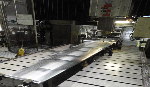
Machining Process
The machining of the keel can start from one of three basic beginnings. The beginnings are a fabricated fin, a cast fin, or a plate of metal or billet. Each of this group of production methods has its own type of information required. Each will also affect the project timing and cost. There is also a further option in machining. There is the ability to machine the bulb, regardless if it is integrally cast on the fin or cast separately. As you can see the options are all possible for the customer.
The beginning of the machining process starts with the receipt of a complete production drawing, including an IGES file. Both of these files have to be complete, all dimensions and surfaces defined. The offered drawings will be used to generate one of the following,
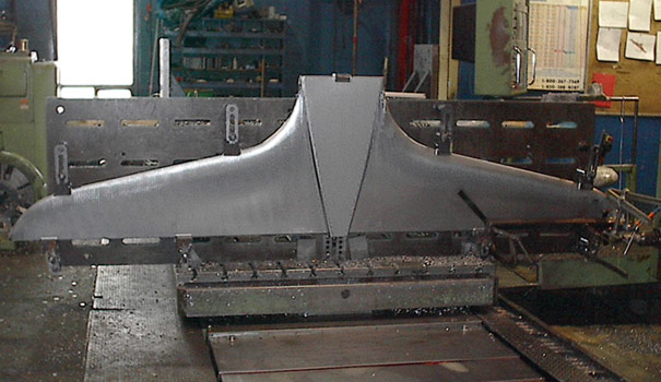
Fin Machining
1. If the keel is to be made from plate steel, or a basic fabrication, the offered drawings are used to produce a rough plate cutting drawing, and secondary fabrication drawing. The rough cutting drawing must also include the positioning of clamping points for milling that are removed at the last stage of milling. The preliminary fabrication drawing includes the machining of all joints and their related weld preparation. The IGES file will be used to create and check the final surfacing program if the fin is to be created from plate steel.
The materials that are available for this process are set by the choices of the designer.
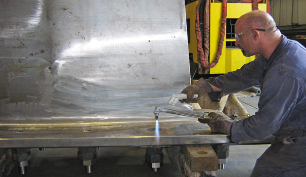
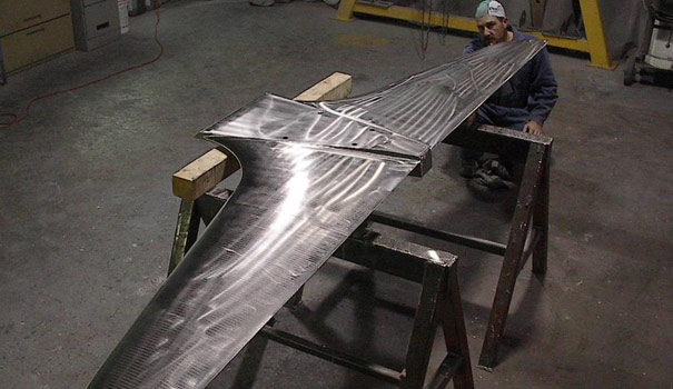
2. If the machining is to begin with a fabricated fin, the offered drawings will be used to produce the initial fabricated fin. The outer surface of the fin will have to be designed and made from plates that are thick enough to allow the machining and still leave the required material thickness on the fin. The IGES file is used for the required surfacing of the fin. The surfacing file is also used in the same way the previous file was used, mill programming and design checking.
The material choice can range from standard Stainless Steel to Armour plate.
3. If the keel is to start off as a cast part, the drawings required are for the generation of the casting pattern. Therefore the required machine tolerance as well as the related shrinkage and possible casting movement must be included in the drawing surface. This is true for both the production of the fin pattern and or the bulb pattern. The only difference is the amount of tolerance required by the different materials and casting methods. The accompanying IGES file is used as before, checking and mill programming.
Bulb Machining
The CNC machining of the bulbs can be done on similar machines, however they require complete environmental segregation from the remainder of the plant as well as a complete prior and post machine cleaning and cutting oil complete change.
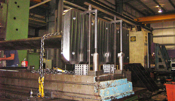
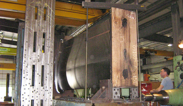
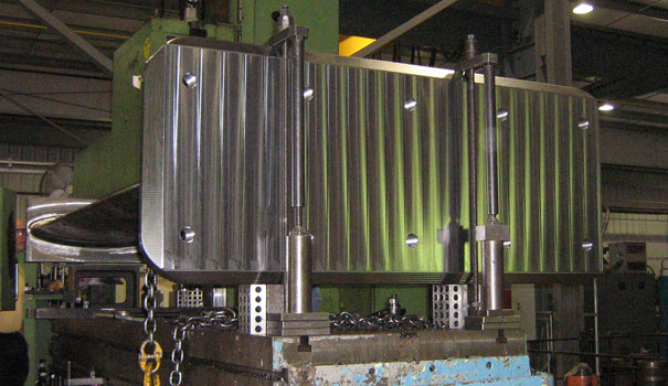
CNC Capacity
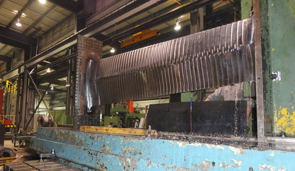
The size of the part it will be CNC machined will determine the size of the mill to be used. We have a maximum Horizontal Boring Mill table size of X-720″ Y- 240″ and a maximum crane lift of 60 tons. This machine size will allow us to mill any keel or fin up to and beyond those generally required by the Maxi yachts.
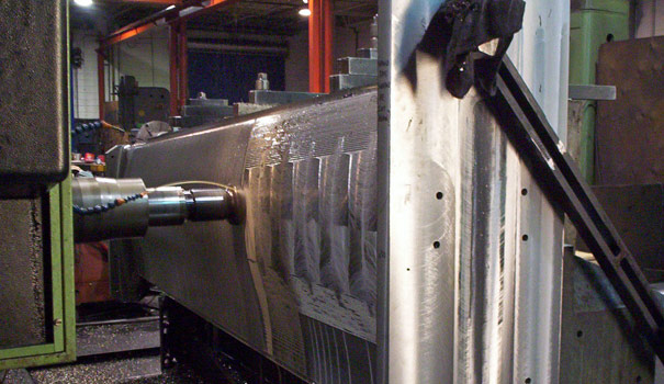
The machined finish surface generally offered from has scallop depth of 0.005″. This can be upgraded to a mirror finish but it would take many more hours on the mill and would offer a surface that is too smooth for the application of primer and barrier coat products.
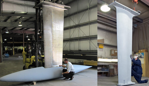
Once the finishing process is complete, the keel is sent to the packaging department where it is prepared for shipping to the customer.